
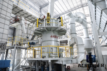
piping and instrumentation diagram of cement manufacturer Grasping strong production capability, advanced research strength and excellent service, Shanghai piping and instrumentation diagram of cement supplier create the value and bring values to all of customers.
 WhatsApp)
Use these shapes for drawing block flow diagrams (BFD), process flow diagrams (PFD), piping and instrumentation diagrams (PID), and water flow diagrams. Get + Dyes Chemical Formulas With Iron. Chemical Engineering Crusher Equipment Symbols. More
A piping and instrumentation diagram (P&ID) is a detailed diagram in the process industry which shows the piping and vessels in the process flow, together with the . process and instrumentation diagram in a cement plant. instrumentation in cement plant - spacekrafterscoin process and instrumentation diagram for cement plant Cementing ...
Maurice Stewart, in Surface Production Operations, 2016. 7.2.9.4 Procedure. To determine the location of pressure breaks, a complete piping and instrument diagram (PI&D) (sometimes called a mechanical flow diagram) is needed.This diagram should show schematically the process and the location of all equipment, valves, controls, and instrumentation.
A P&ID (piping and instrumentation diagram) is a graphic representation of the piping and system components in your process that uses standard symbols and annotations. It plays a big role in the management of a physical process. The ISA5.1 is a standard for P&ID symbols.
Jul 15, 2020· Piping and Instrumentation Diagrams (P&ID) are standardized in many ways, and there are some fundamental safety features that are absolute requirements for all P&IDs. Unfortunately, many people forget these features in their designs unintentionally. Lacking these safety features could lead to serious engineering problems.
Piping and Instrumentation Diagram Documentation Criteria. Includes all amendments and changes through Technical Corrigendum, September 2018. View Abstract Product Details Document History PIP PIC001 (Complete Document ) 2018 Edition, September 18. PIP PIC001 ...
Want to draw piping and instrumentation diagrams? Visual Paradigm's P&ID tool features a handy diagram editor that allows you to draw P&ID diagrams, industrial diagrams, and schematics quickly and easily. The P&ID diagram software comes with a rich set of high-quality P&ID symbols for you to create different kinds of P&ID diagrams.
Process flow diagrams, piping and instrumentation diagram development, full ortho and isometric drawing packages, 3-D plant design modeling, modular and skid design, project walk downs for as-builts, expansion and compliance, and piping retrofit and optimization.
PIPING & INSTRUMENTATION DIAGRAMS (P & IDs) ORIGINAL EDITION OCT. 1996 This standard specification is reviewed and updated by the relevant technical committee on Oct. 2002. The approved modifications are included in the present issue of IPS.
Jul 23, 2020· Piping and Instrumentation Diagram Development. luvogex. 29:08. Instrumentation Loop Diagrams. School. 0:44. tik tok,tik tok 2020,tik tok compilation,best of tiktok,best of tik tok,tik tok best,tiktok best,tiktoks,tok .
Piping and Instrumentation Diagram Documentation Criteria August 2018 Process Industry Practices Page 5 of 60 . bubble: The preferred term for the circle-based symbols used to denote and identify the purpose of an instrument or function. The bubble may contain a tag number. (Synonym for balloon) (Reference . ISA 5.1) design pressure:
Piping Systems. The piping of a single system may contain more than a single medium. For example, although the main process flow line may carry water, the associated auxiliary piping may carry compressed air, inert gas, or hydraulic fluid. Also, a fluid system diagram may also depict instrument signals and electrical wires as well as piping.
Jan 27, 2020· P&IDs, or Piping and Instrumentation Diagrams to give them their full name, are schematic representations of pipelines, equipment, instrumentation, and control systems found in process environments such as Oil Refineries, Chemical Plants, Paper Mills, and Cement Plants, etc.
Jul 04, 2020· Piping and Instrumentation Diagram or P&ID is one of the most important documents for any project. A P&ID is an engineering document developed by process engineers that shows the piping and other related items for process flow. P&ID provides a schematic illustration of the actual processes that are happening in any plant using various P&ID symbols.
After installation I am missing the Piping and Instrumentation Diagram Templates. Per Microsoft support there should be Plumbing and Piping Plan Diagram Templates, however No tabs have been found or exists. On a blank page In Visio 2016 and newer versions: Click Templates > Maps and Floor Plans, and then click Plumbing and Piping Plan > Create.
Process flow diagrams. PFDs show how industrial process equipment is interconnected by a system of pipelines. A PFD is more conceptual than a P&ID, and usually includes more annotations that display data. Create a piping and instrumentation diagram. In Visio, open any of the following templates: Piping and Instrumentation Diagram. Process Flow ...
Jul 11, 2020· These diagrams focus on the flow of information within a control system rather than on the process piping or instrument interconnections (wires, tubes, etc.). The general flow of a SAMA diagram is top-to-bottom, with the process sensing instrument (transmitter) located at the top and the final control element (valve or variable-speed motor ...
A piping and instrumentation diagram (P&ID) is a detailed diagram in the process industry which shows the piping and process equipment together with the instrumentation and control devices.. Superordinate to the P&ID is the process flow diagram (PFD) which indicates the more general flow of plant processes and the relationship between major equipment of a plant facility.
3.8.1 Concrete Containment ..... 3-19 3.8.2 Steel Containment ..... 3-24 3.8.3 Concrete and Steel Internal Structures of Steel or Concrete Containments ..... 3-28 3.8.4 Other Seismic Category I Structures ..... 3-32 Revision 3
Every engineering field has its list of abbreviations to help convey information quickly and easily. Here is such list of abbreviations related to piping engineering. Hope it will be useful to new entrants as well as professionals alike. Sr. Abbreviation Description 1 ANSI American National Standards Institute Inc 2 API American Petrolium Institute 3 ASA [.]
The understanding of Piping and Instrumentation Diagrams is a "must have" skill for Job seekers in several career choices. These include drafting, power plant operation and maintenance, refinery operation and maintenance and workers involved in the construction of industrial facilities.
Sep 03, 2002· To the best of my knowledge there is no ANSI standard for piping and instrumentation diagrams but I will check that. Also I am not aware of any British standard. There is a standard available from the Process Industry Practices (PIP).
Jan 27, 2020· P&IDs, or Piping and Instrumentation Diagrams to give them their full name, are schematic representations of pipelines, equipment, instrumentation, and control systems found in process environments such as Oil Refineries, Chemical Plants, Paper Mills, and Cement .
Jul 11, 2020· Piping and Instrumentation Diagrams (P&ID) are schemes of pipelines, equipment, instrumentation, control systems, from a process system found in Oil Refinery, Chemical Plant, Paper Mill, Cement Plant, etc. The symbols contained in P & ID represent equipment such as actuators, sensors and controllers. Process tools such as valves (valves ...
WhatsApp)